Construction
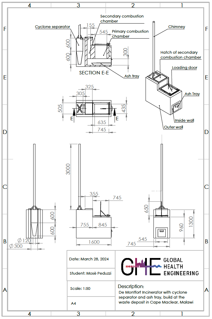
Complete dimensions of the incinerator with cyclone separator are available in the in Figure 1. CAD model of the assembly and the pdf version of this drawing are available in the Github repository in the cad directory.
The first step in the construction of the incinerator is the fabrication of the metal parts, these include:
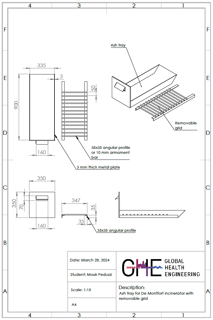
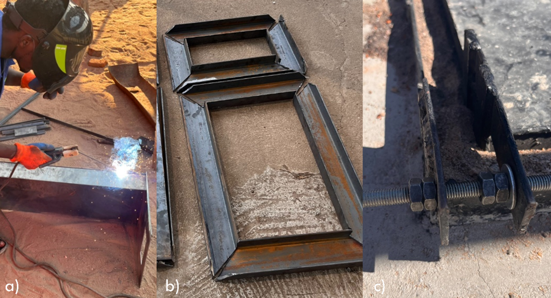
ash tray, composed of a box made of 3 mm-thick metal plates, welded together with a removable grid, build from two angular profiles on the sides. They are connected with a 10 mm armament bar creating a grid on which the unburned waste lays (see Figure 2 for exact dimensions and Figure 3 for construction details).
loading door and its frame, which allow for an easy access to the primary combustion chamber. The loading door is composed of a 3 mm steel plate with angular profiles on the sides. The door is connected to the frame with a hinge and a M 10 threaded bar. The frame has a U-shaped cross-section to seal the movable parts with sand placed in the U-shaped channel.
cover of the secondary combustion chamber and its frame, which allow to close the secondary combustion chamber with a steel plate that is free to dilatate without avoiding leaking of gas and breaking the incinerator’s concrete walls.
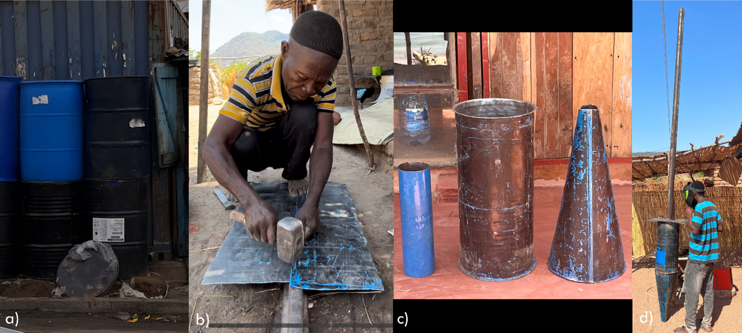
cyclone separator, which was built from a 200 l empty oil drum, cut by hand with shears, a hammer, and a chisel. The barrel has to be opened to create three pieces: the central, cylindrical body, the lower cone, and the inlet tube. The parts needs to be welded together and attached to the chimney and the support plate (see Figure 4 for construction deatils).
All the steel parts have to be painted with a heat resistant paint to prevent them from rusting.
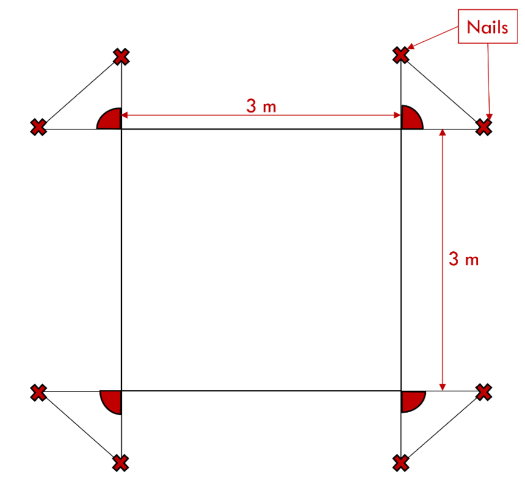
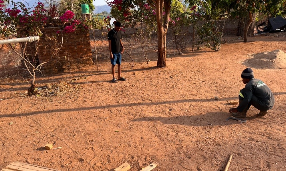
Once all the metal parts are completed, the work at the construction site starts. To elevate the incinerator from the ground and give the all structure more stability, a base of 3 m \(\times\) 3 m has to be built. 8 nails and a string are used to set the boundaries of the base, as shown in Figure 5. Figure 6 shows the place for the incinerator’s construction.
Once the string is in place, the outer structure shall be built with bricks and cement, starting from the corners. Steps in foundation construction are shown in Figure 7.

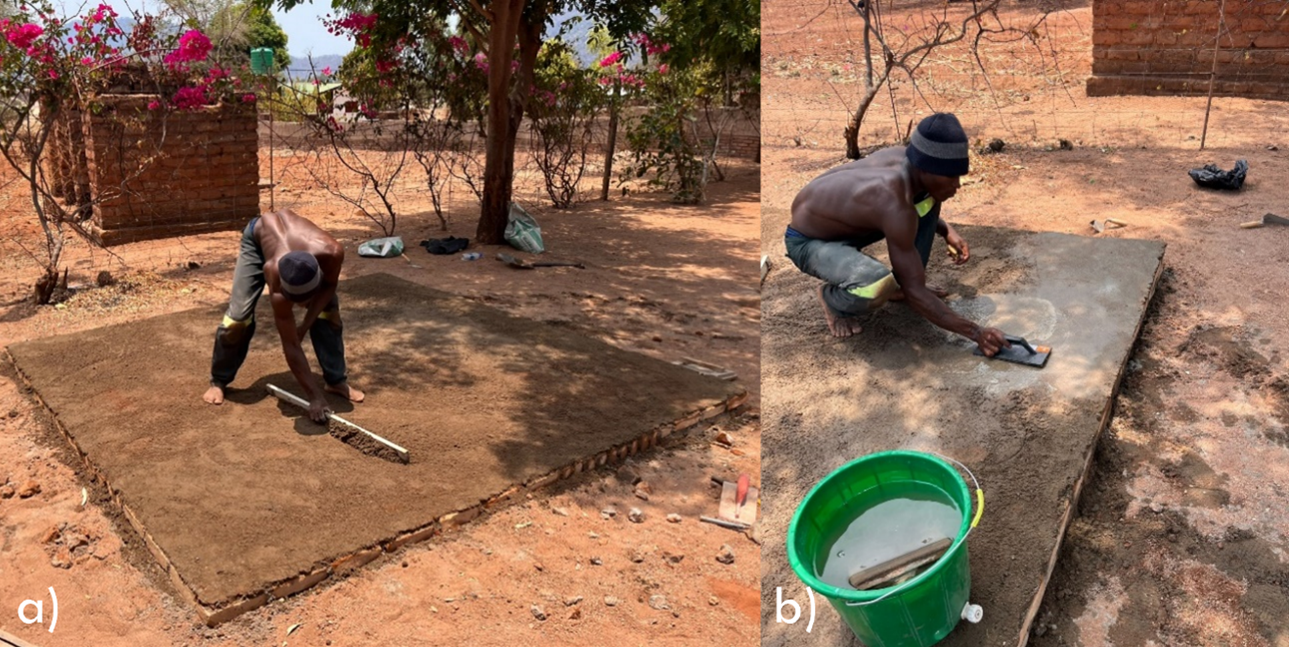
The inner part of the structure is filled with stones and broken bricks in the size of a fist, then covered with dirt and watered. In the end, everythin is covered with a layer of cement - a sponge and a trowel are used to smooth out the surface. Because of expected high temperatures coming from the incineration chamber, and exposure to the sun, it is important to slow the drying of cement by wetting it continuousely for 24 hours. At least 48 hours must pass, after completion of the base, before the first bricks can be laid.
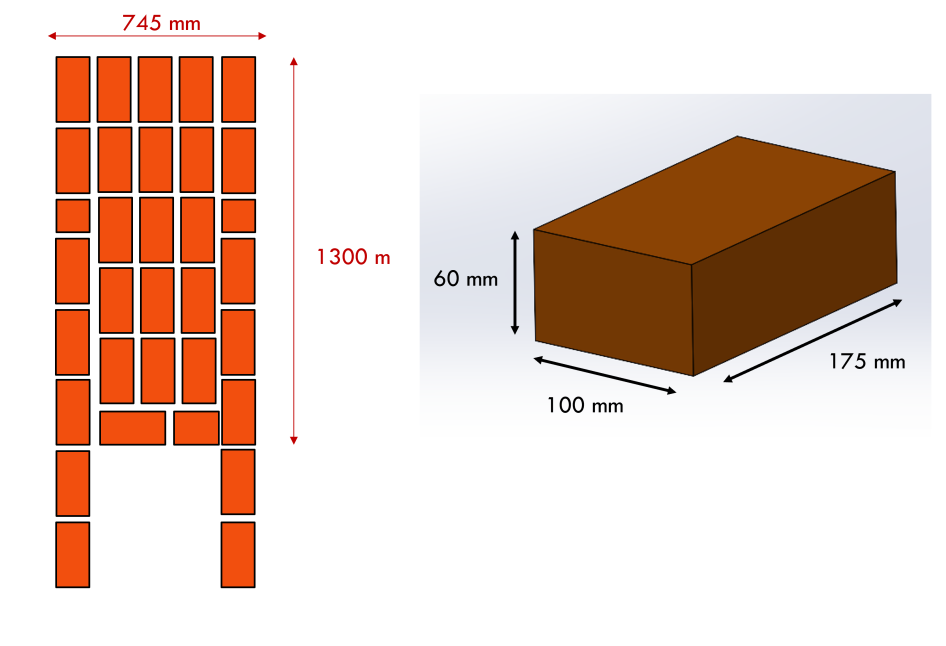
To elevate the drawer from the floor and facilitate its motion, a small base made of bricks and cement, is build following this schematic layout from Figure 9.
On this small base, the ash drawer is placed and used as a reference to lay the first layer of bricks of the combustion chamber wall.
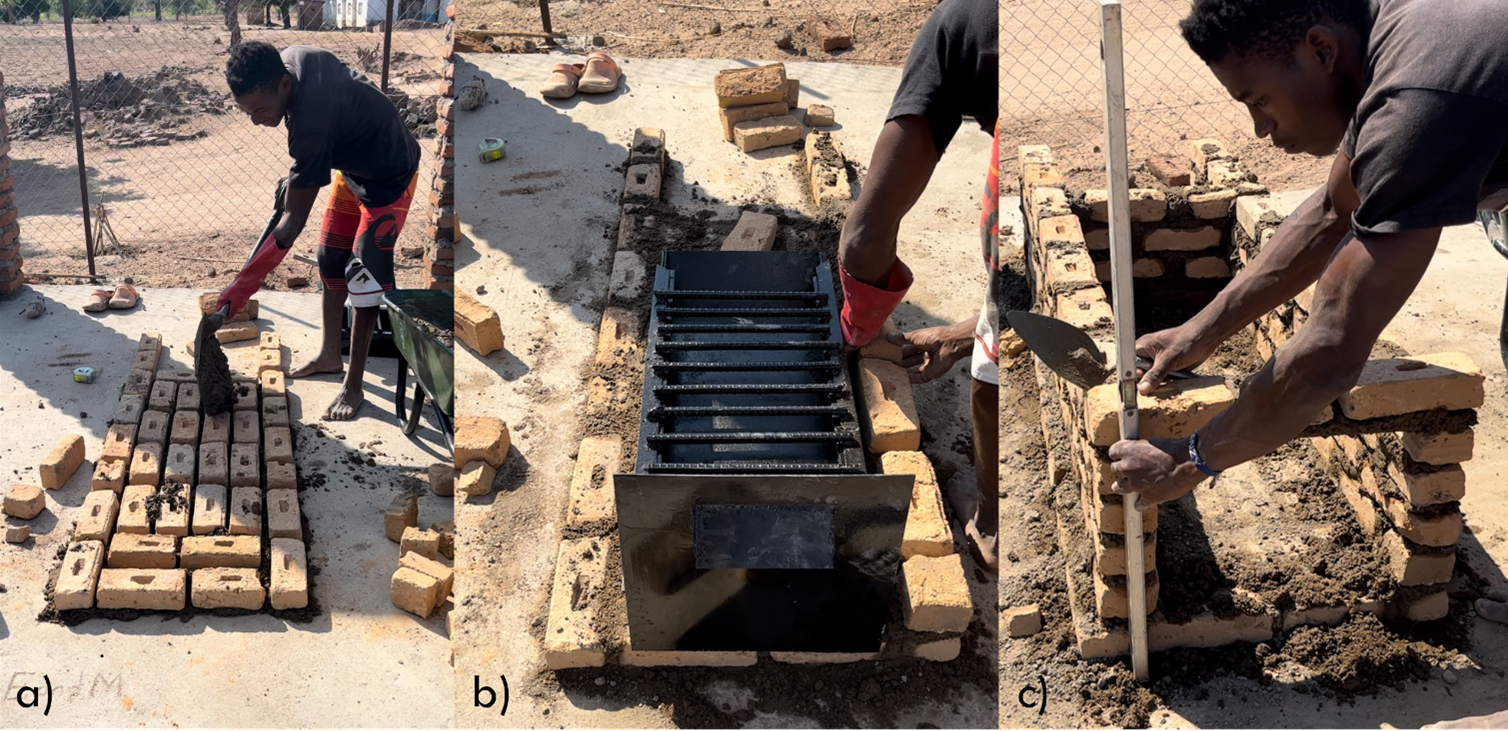
The wall is raised untill it is 30 cm high. At this height reinforcement bars are inserted over the wall using cement, and serving as crossbars. With the created crossbars, the walls are raised untill they reach 1 m in height, when the frame for the loading door can be installed in place with cement.
The walls of the secondary chamber are raised to the height of 1.3 m. Later, the cyclone separator and upper frame of the secondary chamber can be incorporated into the structure.
Once all the parts are set in place and dry, a second layer of bricks is put in place. It is attached to the first one to confer more robustness to the whole structure (see Figure 11).

Plastering work and a roof remain optional and of little impact to the operational conditions of the incinerator itself (more information on them is available in section Extra).